Week 4 - Electronics Design
Redrawing Echo Hello-World Board
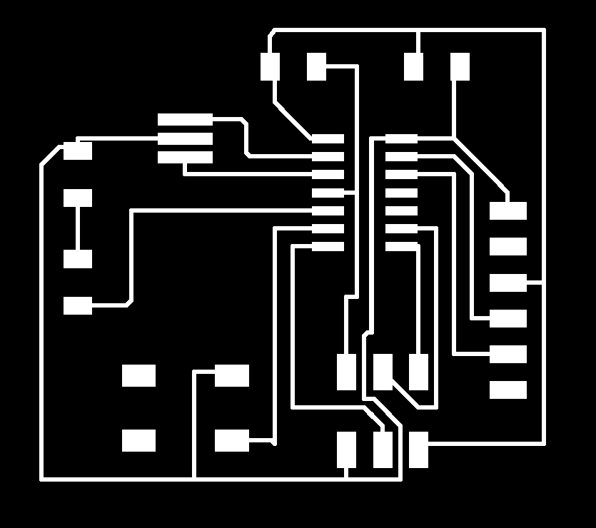
The first part of this week's assignment was to redraw and print the echo hello-world board and add at least a button and LED with current-limiting resistor. The first difficulty for me was understanding what all the components of the example circuit board were.
The suggested software to use was Eagle, which is not the most intuitive program and unfortunately, I had to miss the Eagle tutorial. Luckily, I had Sparkfun and Kevin Jiang, the guy who convinced me to take this course, to walk me through a basic Eagle tutorial (he has a very sophisticated way of explaining how circuits work for anyone who is interested).
To begin using Eagle, I first downloaded and uploaded the FAB parts library, which contained all the components that are readily available in the lab. I added all the components to the schematic, which proved to be a bit difficult as not all the parts were named the same as they were on the sample circuit board. Kevin told me about labelling to connect components together, which made my schematic look a lot cleaner.

The other difficulty I faced was understanding how to connect all the pins. It took me some time to understand which pins were connected together. I also had to mainly guess which pins to add the LED and button too. Hopefully, I will continue to understand circuit boards better as this semester goes on. I then began the board layout, which initially seemed easy...that is, until I got to the last few connections. It took a couple of moving around of pieces and rerouting for my circuit board to look presentable. A tip that I got from the trusty Kevin Jiang was that I could adjust the grid size. This would prevent the routes from being too close together, as the milling machine may combine two routes that are placed too closely. Another tip from the trusty Kevin Jiang was to hide all grey dimensions, so that only the traces would be visible and saved in the image. An oddity I encountered was that the latest version of Eagle does not have the option to export as image anymore. I had to download an older version of Eagle to export my board as an image. What a strange feature to have removed.
Printing and Testing Echo Hello-World Board
Milling was more difficult than last time because Rob was away and I had to use SRM-20 which I had never used before (I used MDX 20 earlier, but I couldn't get the mods server to work). The first trouble I ran into was that endmill was too high and so the first run at milling left the board almost completely in tact. I tried cancelling the run, but the cancel button didn't stop the Roland so I just watched the instrument run for 10 minutes. I then tried setting the z to 0 mm and it seemed to work a lot better. However, this time, only one side of the board milled well.
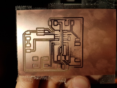
I hypothesized that the problem was with the placement of the circuitboard. I cleaned off the sacrificial board and my circuit board with a single blade and re-applied the double-sided tape. I encountered the same problem again though. Next, I decided to change the sacrificial layer. The third run at milling was successful, but now I encountered a problem with my design. Some of the routing were too close together and some connections were too thin and copper peeled off. I suppose this was a good way to me to learn all the mistakes I can possibly make at milling...
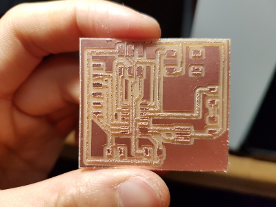
To resolve these issues, I went back to Eagle. To solve the peeling of copper, I changed the width of my routes. To prevent one particular connection from being too close to other connections, I rotated one of my components. My design looked way cleaner now and I milled for the fourth time hoping for the best. Success! Soldering went a lot quicker than in Week 2. My soldering seems to have improved!
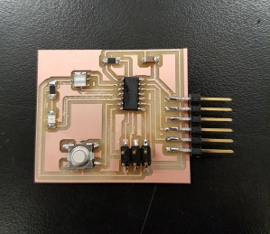
The final part of this week's assignment is to test the board. I decided to test this by programming the button to turn on LED. This is further described in my assignment for Week 6.